
Step-by-step guide to hack camera batteries to charge your devices
To jump straight to making a D-Tap to Cigarette lighter connector, click here.
To jump to the how to video, click here.
How this hack came into being
One of the perpetual problems we face as camera operators and editors, is how the hell do you manage to keep all your batteries charged. I wrote a blog about building your own charging station a few years ago. This has worked well but how often have you been in a pickle and realised that the batteries you need for that other device that you only occasional use on a shoot, aren’t charged up? Well this is how this concept came into fruition.
I tend to find I’m good at keeping my big camera batteries charged, they’re hard to forget, but what about all the little ones; the DJI Mavic Pro 2, the Sony a7s, the DJI Ronin, even my MacBook Pro… the ones you don’t use on every shoot so you sometimes forget to check. Well what if you could charge them up, when your on location, from the big camera batteries. Well that was how the D-Tap to Automobile Auxiliary Power Outlet (or cigarette lighter if you’re old school!) came into being.
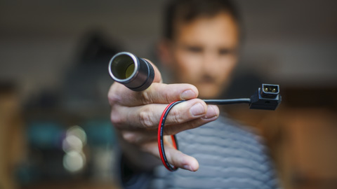
The D-Tap to Automobile Auxilary Power Outlet cable is born!
It’s nothing new, but I realised that my V-Lock camera batteries output between 12-16 volts usually, which is about the same as standard car battery. This meant that technically, something that can run from a car’s cigarette lighter should be able to run from a camera battery. Even electric cool boxes for keeping beers cool on set, if you so wish.
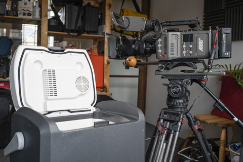
Running an electric cool box off my ARRI Amira
Initially I started off by adapting individual adapters, including my DJI Mavic Air charger. There didn’t seem to be an affordable, reliable solution to charge drone batteries when you’re out and about. The point is, DJI would rather you buy more batteries than be able to charge your existing ones when you’re on location and they are run down. So I started by sticking a D-Tap connector on my Mavic Air’s charger. This worked perfectly but as I’ve upgraded to the DJI Mavic Pro 2 and ended up with a new set of chargers, I realised that adapting everything could become tiresome. Hence I came up with the idea of having one cable that could charge everything.
Charging a MacBook Pro from a battery
The other advantage to this system, is that it can charge a MacBook Pro via USB-C whilst mobile. You can buy power banks with USB-C outs, you can even buy camera batteries with USB-C outs, but it’s very hard to find anything which can keep a MacBook Pro charged up whilst I’m using it. As so much power is drawn whilst editing, I found my MacBook Pro’s battery would discharge even when plugged into a power bank.
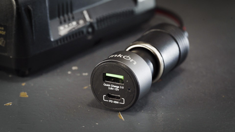
A USB-C adapter that outputs 45w
This is because typically a standard power bank with USB-C outputs around 20-30 watts. My 15” MacBook Pro charger outputs 87 watts which is why the battery can charge up, whilst I edit. Using this D-Tap to Cigarette lighter system, you can buy a USB-C adapter which outputs the full 87 watts if you so wish. I’ve ended with one that outputs 45 watts and that seems sufficient so far.
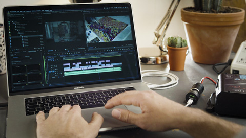
Running my MacBook Pro whilst editing off of a V-Lock battery
How to build a D-Tap to Cigarette Lighter cable
First up, we need to start with a warning. This article demonstrates how I created my cable for my use. I’m in no way qualified to issue advice on anything electrical. This guide is to be used for entertainment purposes only. If you choose to copy me, then you do so at your own risk!
I’ll start with the potential issues of getting this wrong…
- If you cross the wires (i.e. the negative and positive touch) you will short the battery out which can cause a fire
- If you get the negative and positive side the wrong way round, the polarity will be reversed this could potentially damage the equipment and again start a fire
- Never leave batteries unattended whilst charging. If anything overheats, it will again start a fire
- You must check, that anything you plug into this is rated to be powered with between 12-16 volts.
- This is based on the batteries I have, which are IDX V-Lock batteries with D-Tap outs. However, this should work with any battery that outputs between 12-16 volt (Anton Bauer, PAG, CoreSWX, Gold Mount, etc..) that either have a D-Tap out or can be connected to a battery plate that outputs a D-Tap connection. Smaller batteries, such Sony NP-F batteries, as standard don’t put out enough voltage for this method to work.
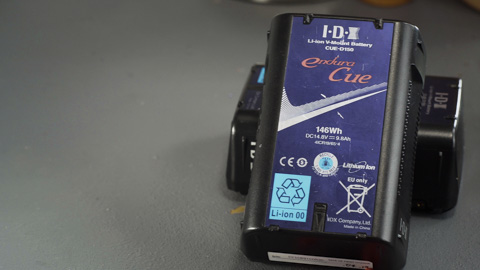
IDX V-Lock Camera Battery
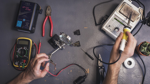
Equipment Required:
Pliers
Wirestrippers
Small Screw Driver
Heat Gun (or lighter at a push!)
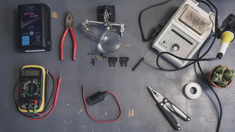
Components Required:
Female Cigarette lighter with short wire
Solder
Heat Shrink
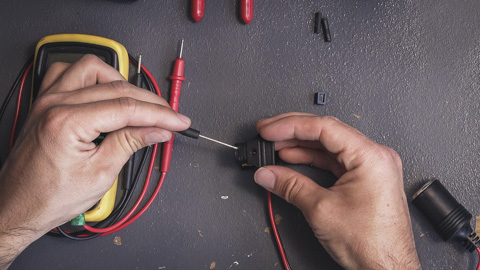
Step 1 - Line Up the connector
Start by lining up the D-Tap connector and figuring which side of the connector you want the tail end of the wire to come out. Generally, D-Tap connectors can be wired to come out either side of the plug. Once you’ve got the orientation figured out, note which pin will positive and which will be negative. In my example here, the top pin (noted on the casing of the plug and battery) is positive and the lower pin is negative. The longer pin should be the top pin (one furthest from wire entry point) and the shorter pin the lower pin (one closest to wire entry point).
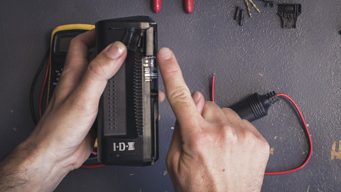
Line up connector and figure out the side for the wire to come out
Example of choosing the correct side for the wire to come out of
Figuring out which pin is positive and which is negative
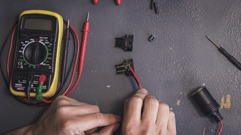
Lay everything out and ensure you understand what goes where.
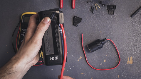
Step 2 - Trim the wire
Trim the wire to length. In my example, as the positive is the top pin I leave that the length it is and then remove 5-10mm of the negative. With that trimmed, strip a small section of the wire to expose the strands. Twist the strands to keep them together
Cut wire and strip sleeve (ideally with the proper tools and not a leatherman!)
Twist the wire strands together
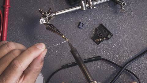
Step 3 - Tin the wire
You now want to tin the wire. Tinning is the process of applying some solder to the end of the wire or terminal you intend to solder. This is what you’ll eventually melt to connect the two together.
You start by clamping the wire so don’t need to hold it. Then with a soldering iron set to a medium-high heat (I set mine to around 330℃), ensure the tip is clean by wiping on a damp soldering sponge.
Clamp wire and clean soldering iron tip
Now the correct way is to add a small spot of solder to the end of the iron, then hold the tip of the iron next to the strands of the wire, in one smooth movement push the solder wire into the tip of the iron as you move down the length of the strands. If done correctly, you should have a layer of solder on the strands. Then immediately flick the end the wire with the tip of the iron to flick away and excess solder. N.B. This is the way I tin a wire, if you don’t know how to this, I’d probably suggest learning how to do it properly first rather than following my cack-handed way!
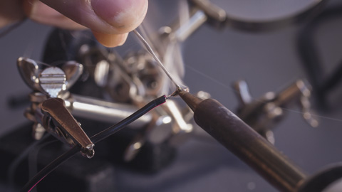
Tinning the wire
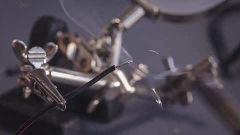
Flicking excess solder off of wire
Now, I finally end by trimming the end of the wire so I just have around 5mm exposed wire to attach to the terminal.
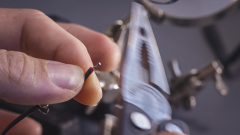
Trimming wire to correct size
With the wire I’m using, it comes pre-tinned on the exposed wire, so I only need to tin the negative side which is the side I cut to length.
Now place heat shrink on the wire. In my example, I’ve placed a slightly larger piece on both the positive and negative wires to keep them from splaying. I’ve then used a small piece just on the positive side. This will help ensure, that if the two wires come into contact, the shrink will insulate them and prevent short circuiting.
Add heat shrink to wires now
Step 4 - Tin the terminal connectors
Now tin the terminals. I start by clamping them and melt a small amount solder into it.
Tin the terminal connector pin
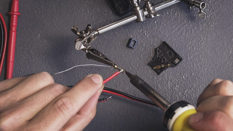
Step 5 - Solder the wire to the connector
Now touch the pre-tinned wire next to the connector and heat them up with the soldering iron. Given a few seconds, the solder will melt, smooth out and join together.
Solder the connector to the wire
You can now remove the terminal from the clamp. Once it’s cool, the wire and terminal should be locked together. If not or if it comes apart, it’s likely to be a bad solder. There’s numerous reasons this could happen, including the solder iron being set too hot. I’d clean the wire and terminal off and start again.
Now repeat process with other terminal and wire. With the two wires and terminals soldered together, slide the heat shrink over and heat up (with a heat gun ideally or lighter if you’ve not got one to hand).
Step 6 - Assemble D-Tap Connector
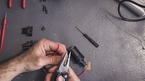
Now put the assembly together. I find that these connectors can be a bit snug, but as long as the wires aren’t touching, once it’s all squeezed together they hold perfectly fine. Use the pliers to clamp the wire cable clip. This helps prevent the wire being yanked out the connector.
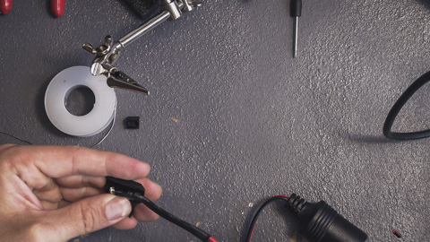
Now assemble the connector
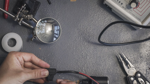
Screw it all together
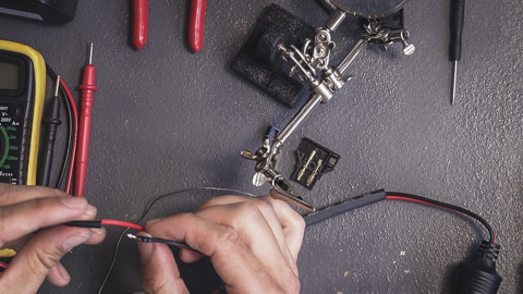
Step 7 - Testing
Before plugging this into anything, you want to ensure that everything is wired correctly. Using the multimeter, check continuity between the centre pin on the aux socket and the positive pin on the D-Tap connector. Then check continuity between the sleeve and the negative pin. If all is OK, check there’s no continuity between the two pins. If there is, then you’ve shorted the cables somewhere. Best take it apart and try again!
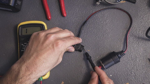
Test for continuity
Now you plug it in. Once it’s connected to a battery, with the multimeter set to 20v DC measure the voltage from centre pin on the aux end and the sleeve. You should be getting somewhere between 12-16 volts.
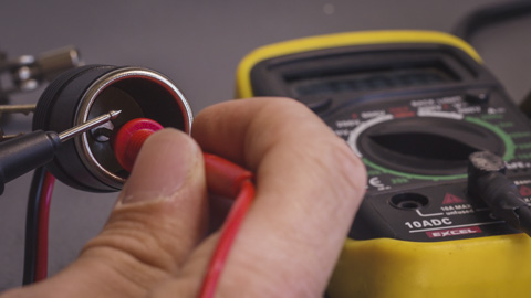
Test voltage from the battery - it should be 12-16 volts
If that’s all correct, then you’re ready to use it.
Summary
And so there we go. This should hopefully be a fairly simple project to get started soldering. The components are quite big and it’s a little more forgiving than working on tiny circuit boards. As mentioned before, whenever you charge Li Po batteries, fire can be a risk. This is no different so I would never leave this charging unattended.
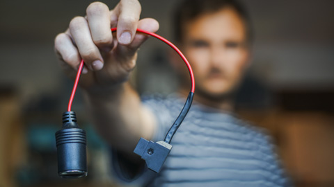
How the final cable should look
Anyhow, I hope you find this useful and hit me up if you’ve got any additional questions or comments.